

Start With the Right Definition
A sprinkler zone, sometimes called a station, is one electrically controlled valve circuit. When the controller activates Station 3, that valve opens and every sprinkler or drip emitter downstream of it runs together. A zone is not one sprinkler head, one controller program, a USDA plant-hardiness zone, or automatically one visible part of the yard.
That distinction prevents the most common counting mistake. A lawn may contain 30 heads but only six valves, so it is a six-zone system. Conversely, a modest yard can have eight zones when turf, trees, drip beds, sunny slopes and shaded areas need different runtimes.
What You Need Before Mapping
- Your controller and its zone or station buttons
- A phone or printed sketch of the property
- A pencil and eight different marks or colours
- A second person, if the controller is far from the yard
- Closed shoes and daylight so leaks and broken heads are visible
Step 1: Read the Controller Without Disconnecting Anything
Open only the normal user-access panel. Look for terminals labelled 1, 2, 3 and onward, plus C or COM for the common wire. Some systems also show MV, P/MV or PUMP for a master valve or pump-start relay. Those special terminals do not necessarily represent another watering area.
Record three numbers separately:
| Controller observation | What it tells you |
|---|---|
| Highest numbered terminal | Maximum physical capacity, not the number in use |
| Numbered terminals with field wires | Likely connected stations |
| Stations that actually run water | Active irrigation zones |
Step 2: Run One Station at a Time
Choose the controller’s manual single-station mode—not “run all programs.” Start with Station 1 for two or three minutes. Walk the property and mark every operating head, bubbler or drip area. Note the first visible spray, because a distant rotor zone may take time to pressurise.
Stop the station before starting the next one. Running two zones together can reduce pressure, blur the boundary and produce a false diagnosis. Repeat for every numbered station, including wired stations that appear unused.
For each zone, record:
| Field | Example |
|---|---|
| Area served | Front sunny lawn |
| Emitter type | Gear-driven rotors |
| Plant type | Warm-season turf |
| Sun/exposure | Full afternoon sun |
| Visible problems | Head 3 low; overspray at path |
| Controller result | Runs normally / silent / intermittent |
Step 3: Draw Boundaries, Not Just Dots
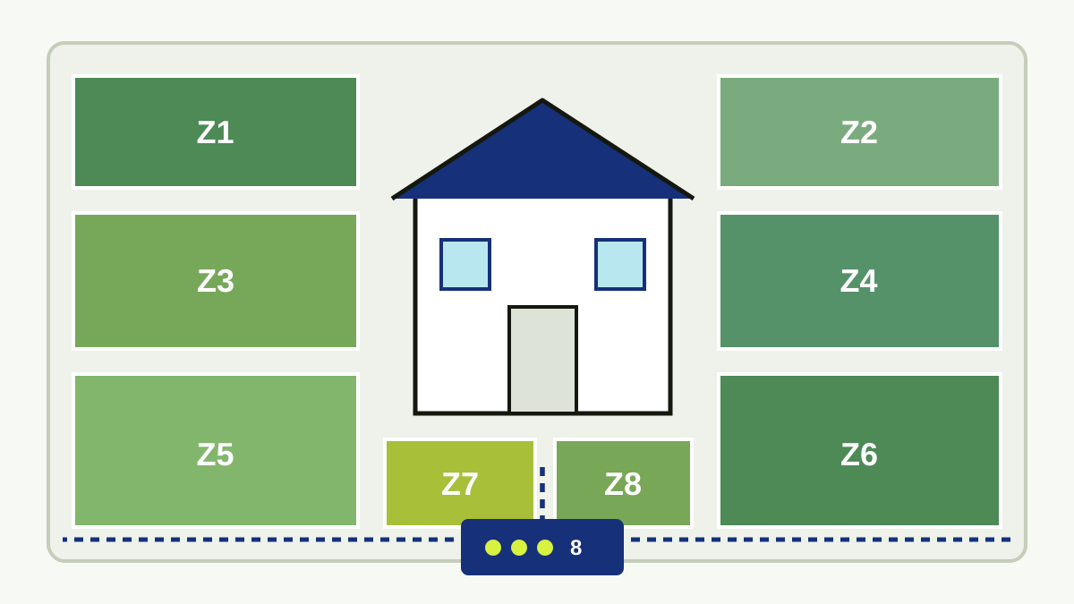
Mark the approximate wetted area rather than drawing only sprinkler heads. Adjacent zones often overlap by design, and “head-to-head” coverage can make two circuits look like one. Use a separate outline or colour for each controller station and label it Z1, Z2 and so on.
Also distinguish fundamentally different equipment. Spray heads, rotors, dripline and bubblers apply water at different rates. If one electrical zone mixes them, write that down; it may explain why one section is soaked while another remains dry.
Step 4: Interpret Silent and Partial Zones
A station that produces no water is not proof that the zone never existed. Record what happens before replacing the controller.
| What you observe | Plausible causes | Safe next check |
|---|---|---|
| Controller shows running; no water anywhere | Closed supply, valve fault, broken field wire or abandoned station | Confirm other zones run and inspect only accessible valve boxes |
| One head rises weakly | Clogged nozzle, leak, low pressure or too many heads | Look for pooling and compare nearby heads |
| Valve opens manually but not from controller | Programming, terminal output, solenoid or field-wire fault | Photograph wiring and call a technician if electrical testing is required |
| Water appears outside the mapped area | Cross-connected pipe, unrecorded extension or mistaken boundary | Stop, remap and check which station is active |
Step 5: Find Valve Boxes Only When Necessary
The controller map is enough for scheduling. Valve-box locations become important when a station is silent, leaking or being expanded. Typical clues include a green round or rectangular lid near the irrigated area, a row of boxes near the water source, or a slight depression in the soil.
Never probe blindly where electrical, gas, communication or irrigation lines may be buried. Use property records, an irrigation contractor or an appropriate locating service when a box cannot be found visually.
Your Finished Zone Schedule
Once the map is complete, group zones by what they water—not merely by number. Turf rotors may need longer cycles than fixed sprays; drip beds usually need lower-frequency, deeper watering; slopes may need cycle-and-soak; and shaded areas usually need less water than exposed turf.
The map should answer four purchasing questions:
Only after those answers should you compare controller capacity. Until the detailed capacity worksheet is published, use our current smart-irrigation controller guide and zone resource hub to organise the next decision.
Printable Eight-Zone Worksheet
Print this page or copy the table into a notes app. Leave unused rows blank rather than inventing zones.
| Zone | Area and boundary | Emitter and plants | Sun / slope | Faults or notes |
|---|---|---|---|---|
| Z1 | ||||
| Z2 | ||||
| Z3 | ||||
| Z4 | ||||
| Z5 | ||||
| Z6 | ||||
| Z7 | ||||
| Z8 |
When to Call a Professional
Use a qualified professional when the controller contains damaged or wet wiring, a pump-start relay, unfamiliar high-voltage components, repeated blown fuses, buried valves that cannot be located safely, or a zone that stays open after the controller stops. Mapping should reduce guesswork; it should not turn diagnosis into unsafe electrical or excavation work.